
Stage 1: Target Board Image Retrieval
Firstly, the image taken from the camera needed to be cropped and aligned. The program ImageAlignment.cpp implemented two methods to achieve this.
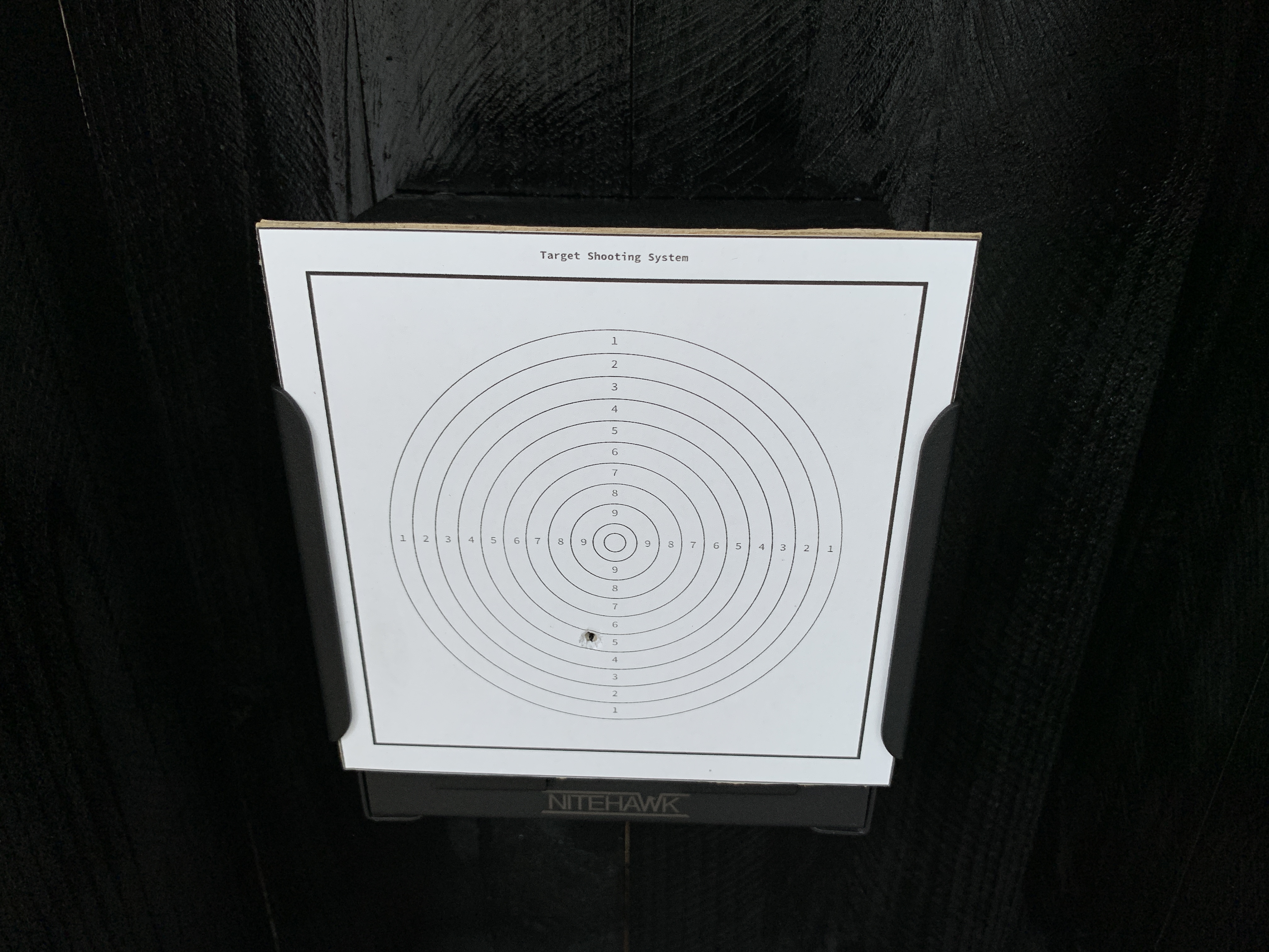 Image taken from the camera
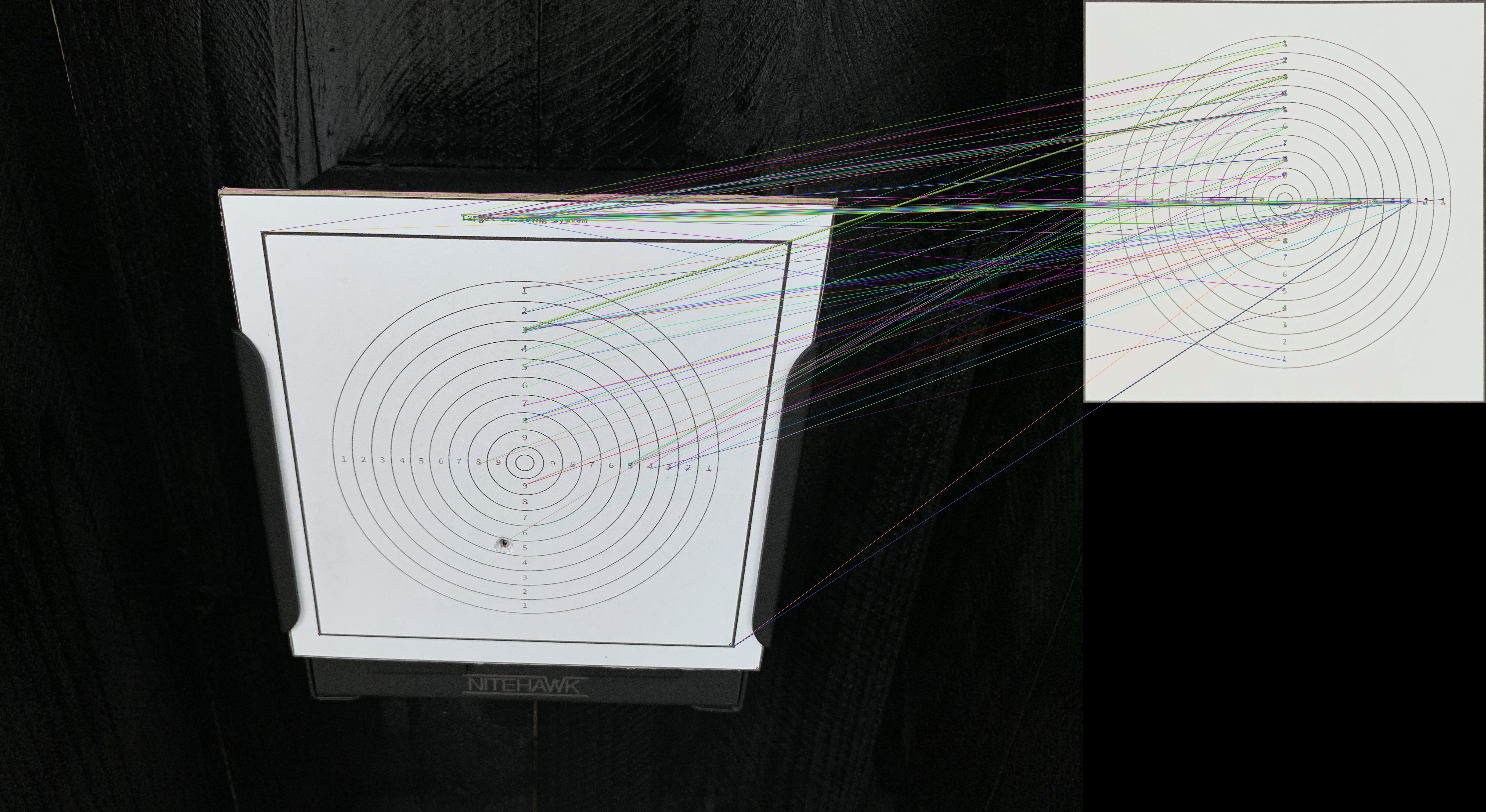
Method 1: ORB Matching
For this method, a shot image and a model image are passed as input, as we use the model image to align the image taken from the camera. The process is similar to the paper scanner on a phone, which aligns the document or paper from the image that you have taken based on an existing template.
The method here uses the ORB (Oriented Fast and Rotated Brief) to match descriptors between images taken by the camera and the template image. The algorithm is currently the most robust and accurate one out there.
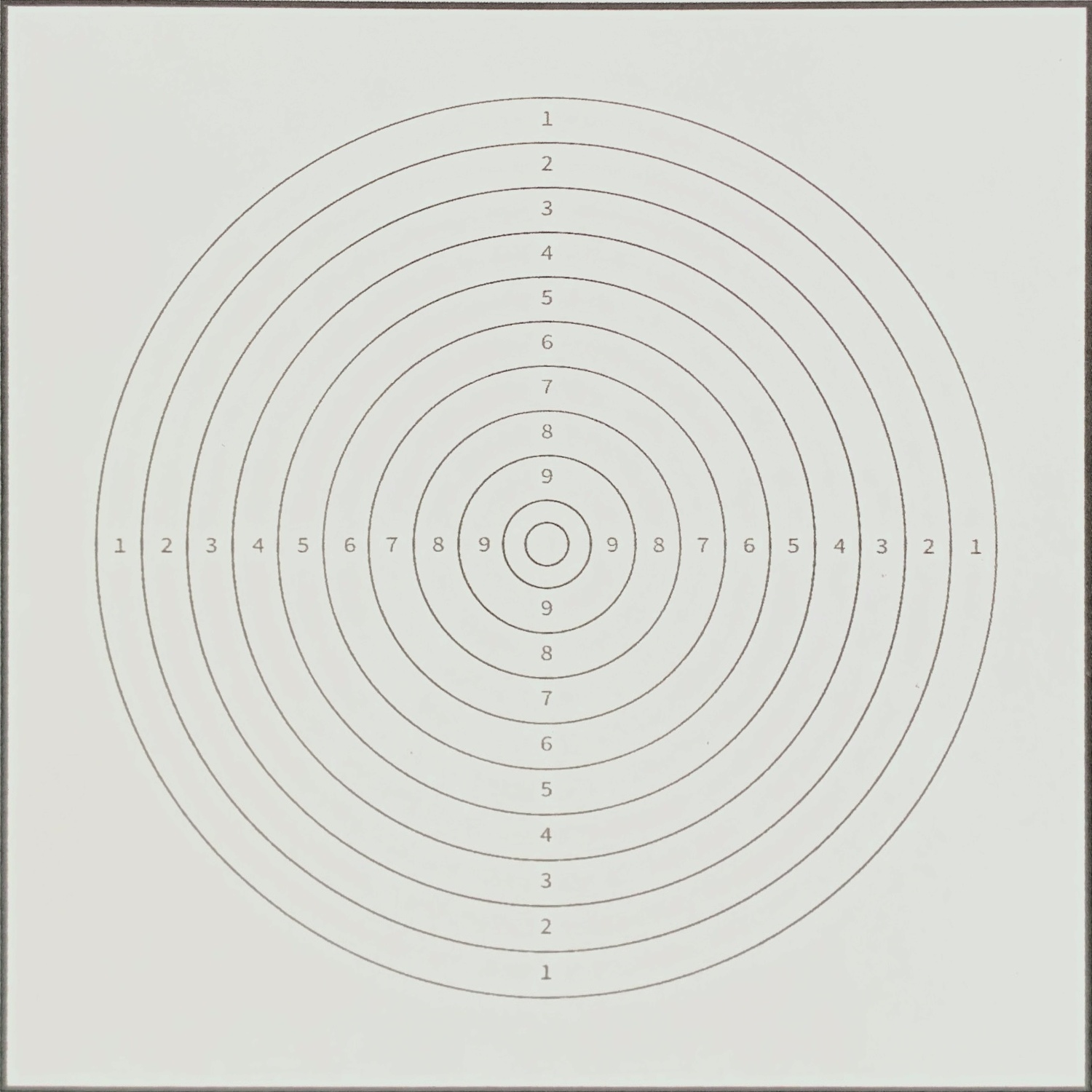 Reference Target Image
Then, a ratio test is performed to obtain only those good matches. The matches are shown as follows: In this case, 35 matches were found good_matches.size() = 35
Provided we have enough key-point matches and correspondences, we can then compute a homography matrix, which allows us to apply a perspective warp to align the images.
1
2
3
4
5
6
7
8
9
10
11
// find homography
cv::Mat homography;
if (good_matches.size() >= 4)
{
    homography =
        cv::findHomography(input_img_matched_keypoints, ref_img_matched_keypoints, cv::RANSAC);
}
else return -1;

cv::Mat warped_img;
cv::warpPerspective(input_img, warped_img, homography, reference_img.size());
The warped output image looks like this: All output images are the same size as the template image, which is 1080x1080px. Then we can pass it down to the next stage.
 Output Image
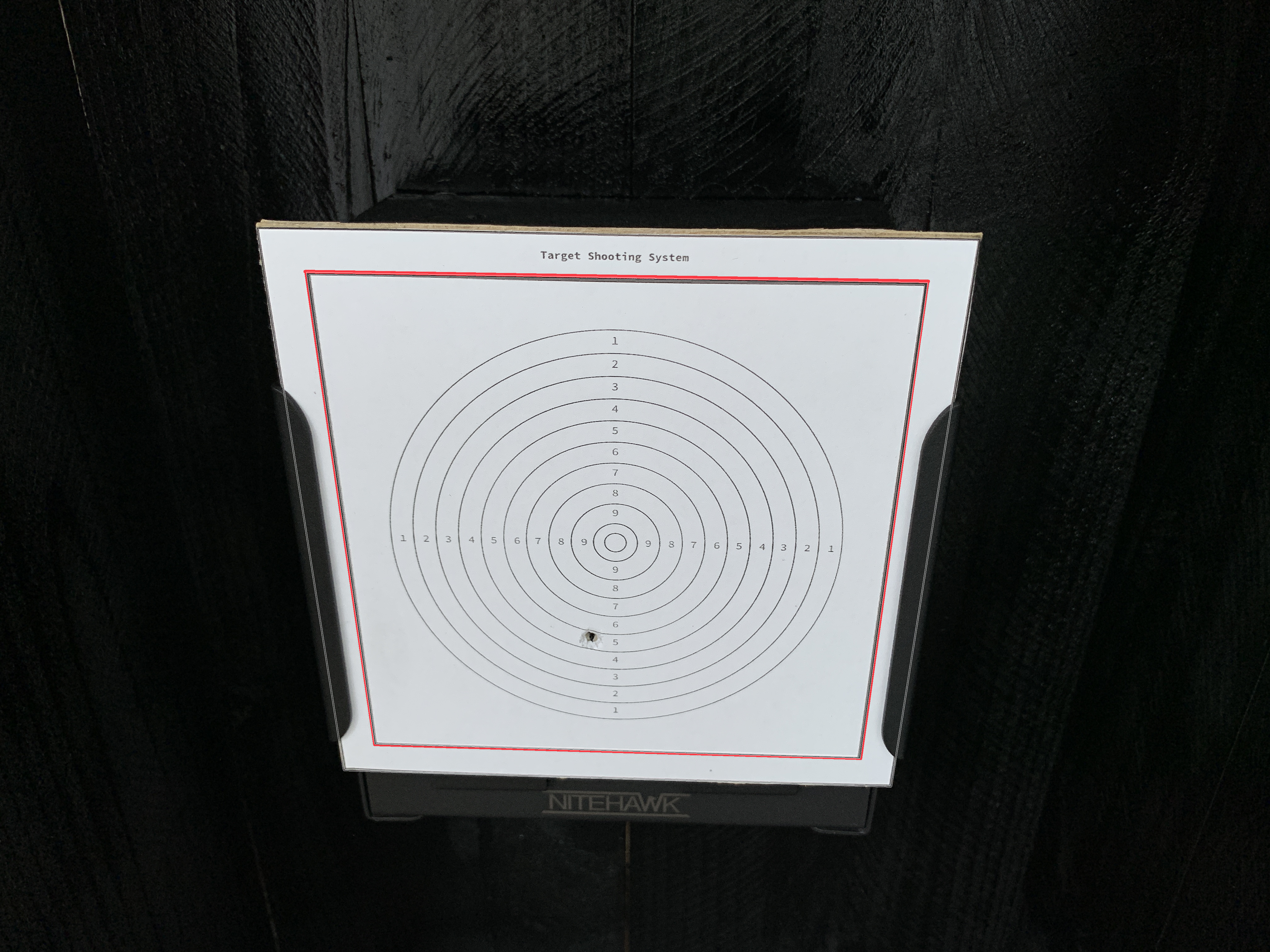
Method 2: Shape Detection
The second method also finds homography and warps the perspective into the correct shape. But it uses a different method for finding homography, which is shape detection. The reason that I think this approach would work better in this specific application is because a template image is no longer needed. But in order for the first approach to be effective, the template image has to be taken, and any difference between the template image and the actual image can vary due to a lot of reasons (like printing, paper materials, etc.), which results in inconsistent matching results. But for the second approach, the idea is to find a general pattern of shapes in those images, which is pretty straightforward in this case.
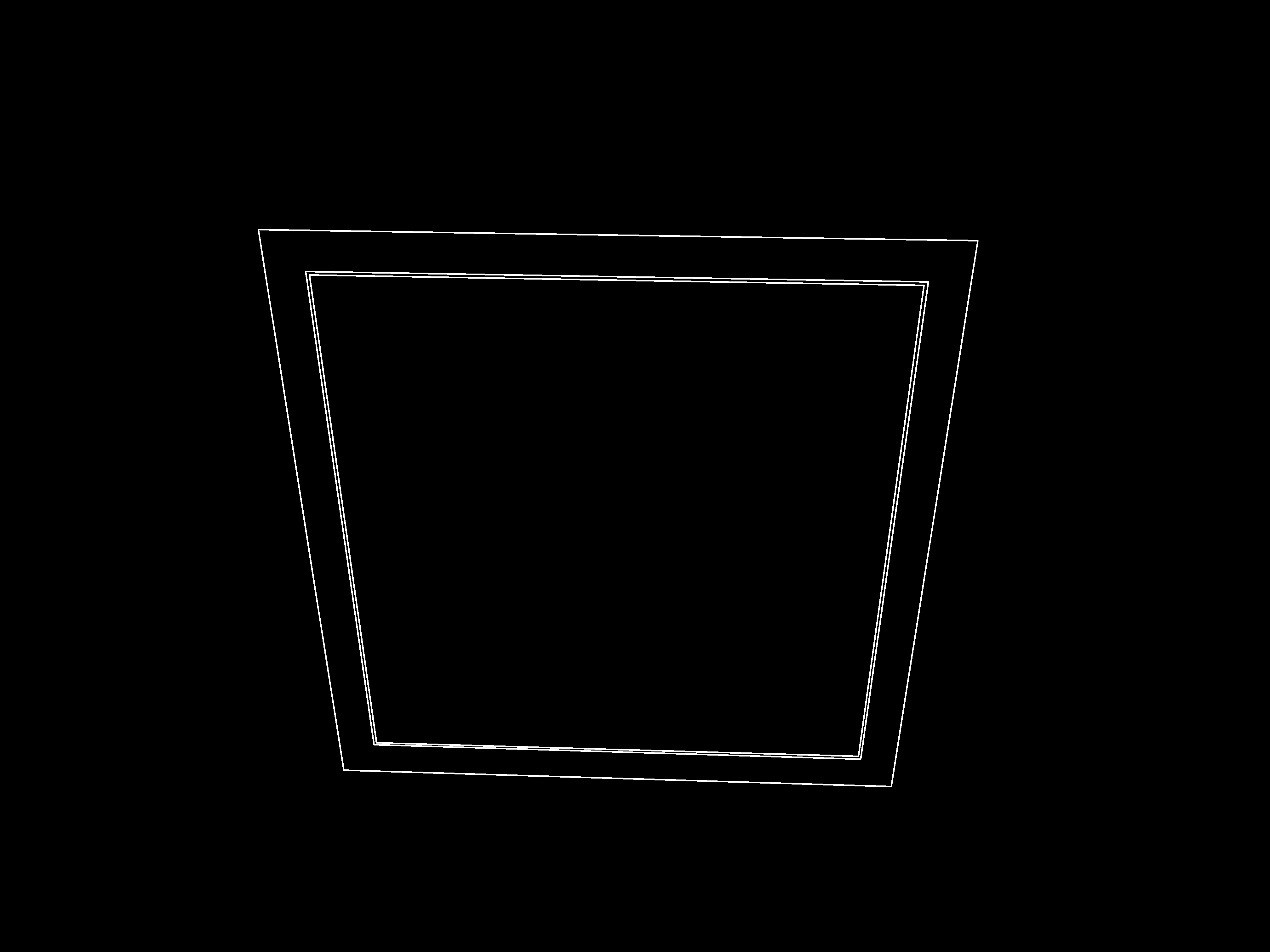
The current implementation uses approxPolyDP() to find polygons from the image, and square contours should have 4 vertices after approximation, a relatively large area (to filter out noisy contours), and be convex. Lastly, to control the level of tolerance for the approximation, we need to define an epsilon value that is relative to the perimeter length since a value that will work well for some shapes will not work well for others (larger shapes versus smaller shapes, for instance). Doing this ensures that we achieve a consistent approximation for all shapes inside the image. Reference to: cvexplained: Contour Approximation
And those are all the square contours we get from the input image:
 Output Image
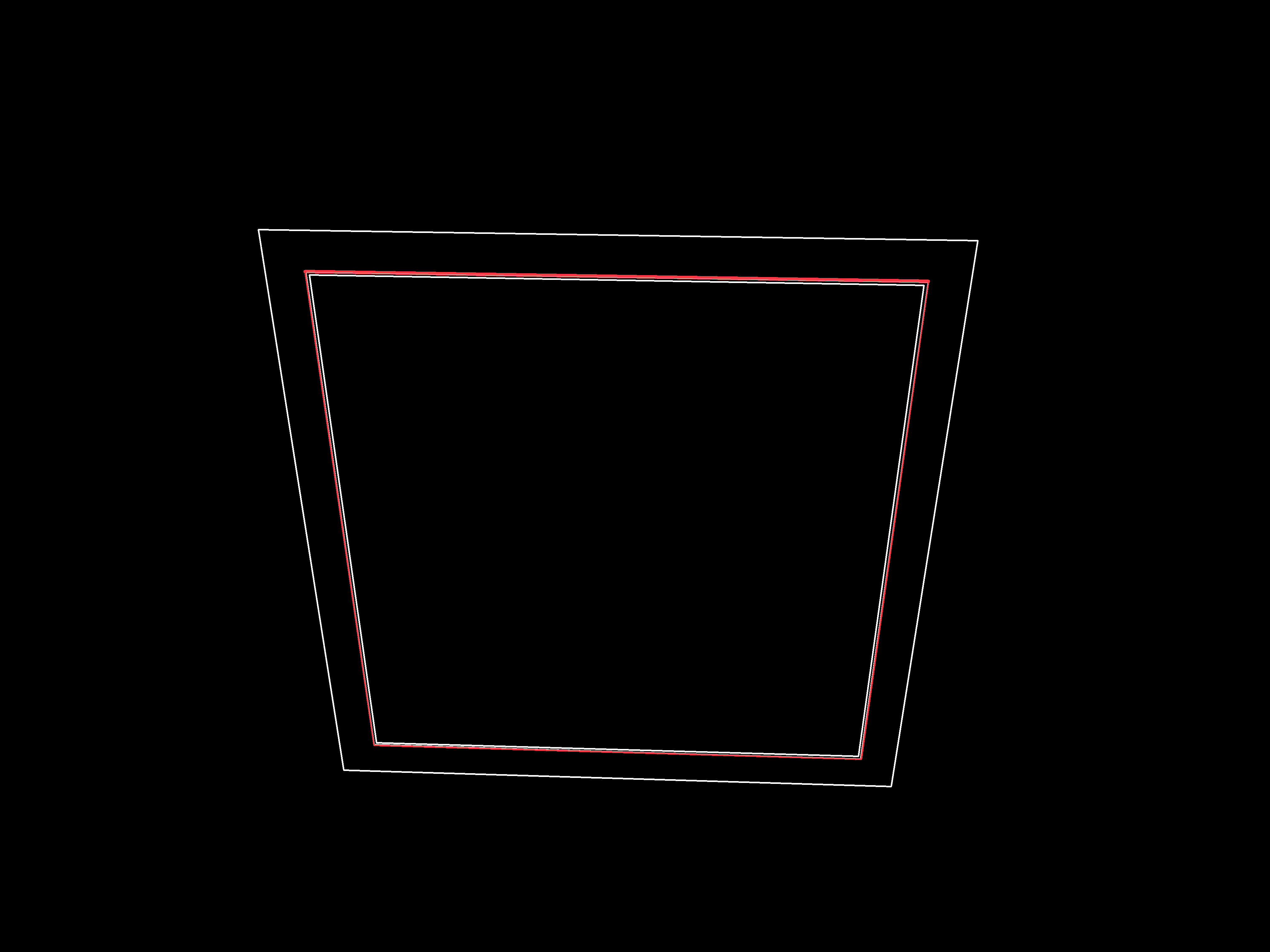
Contours will get sorted based on their areas, and the square contour with the second largest area will get selected for finding homography.
 Output Image
 Output Image
The warped output image, again, looks like this. But here, the output image could have different ratios for height and width, so we rescale them to 1080x1080px and pass it down to the next stage.
Output Image
Stage 2: Computing the Shooting Score
The programme in ShootingScore.cpp implements the next stage of the project, which is extracting useful information from the processed image and calculating a final score for the user.
The first step is to process the image again into different forms:
- Greyscale Image: For storage purposes, the B&W image already contains sufficient amounts of information.
- Blurred Image: Noise Reduction
- Binary image: contour/edge detection
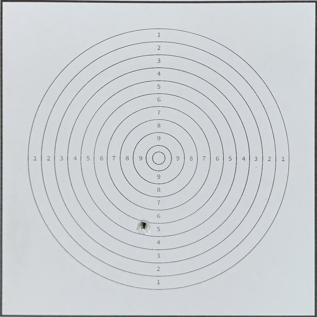
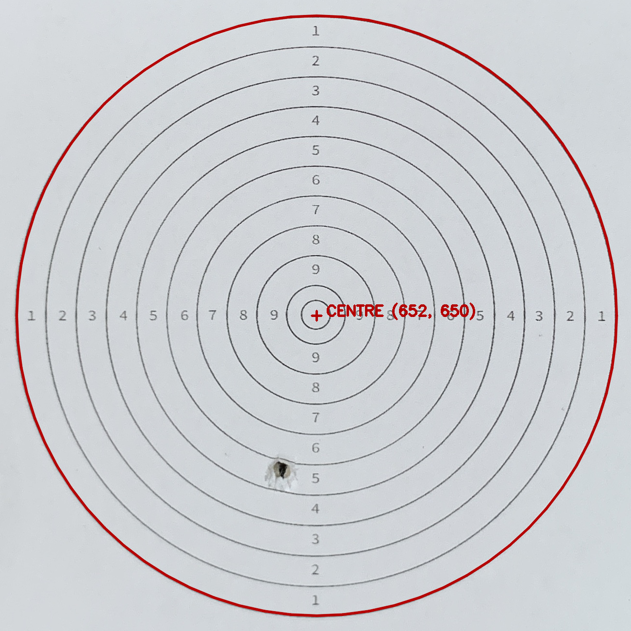
Then the contour shape detection can be applied on top of the blurred image to establish where the target centre is. Because the centre is established when the target ring comes off the board. For better accuracy purposes (the image can get wrapped or bent, which can effect the relationship between the target rings and the centre), multiple rings are used to calculate an average target centre location. Additionally, we can calculate the radius between the centre and the outermost ring, as this is required for the final score.
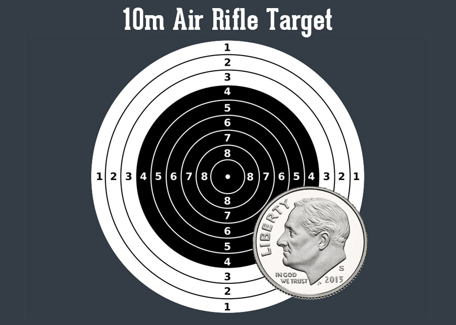
50m RIFLE 3 POSITIONS MEN:
The 50m Rifle 3 Positions Men is an ISSF event where athletes shoot over a distance of 50 meters or 54.68 yards in kneeling, prone and standing positions, using a 5.6 millimetres or 0.22 inches calibre rifle, with a maximum weight of 8.0 kilograms or 17.64 libbers.
The center of the target is positioned at 0.75 meters above the floor and its total diameter measures 154.4 millimetres. The diameters of the fourth ring is 106.4 millimetres, while the tenth ring measures 10.4 millimetres
 Target Outline
Now we go on to track where the new shot is by comparing the current image with the image we have taken previously (before the shot). The idea is that the new shot location can be obtained from the difference between the two images. Both images have to get blurred for this method, as any slight change in illumination or viewing angle will get shown as the differences between the two, so noise reduction is important here. A binary image is obtained as the difference between the two, and we can apply an additional dilation algorithm on top of the image for further noise reduction.
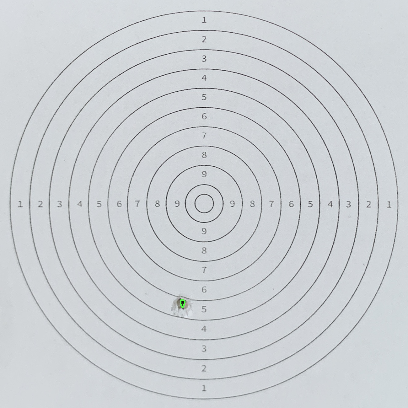 Shot contour
The shot location can then be calculated as the centre of the above contour. The centre of an irregular shape can be calculated with a for loop as follows:
1
2
3
4
5
6
7
8
9
10
11
12
13
14
15
16
17
18
19
20
21
/* uses shot contours to cumpute the shot location */
void ShootingScore::computeShotLocation()
{
    shot_location = cv::Point(0, 0);

    // as the shot contour can be irregular,
    // we need consider all shapes,
    // and compute the actual centre of all contours
    for (auto &&contour : shot_contours)
    {
        cv::Point contour_centre;
        util::getContourCentre(contour, contour_centre);
        shot_location.x = shot_location.x + contour_centre.x;
        shot_location.y = shot_location.y + contour_centre.y;
    }

    // get a average centre of all contours
    shot_location.x = shot_location.x / shot_contours.size();
    shot_location.y = shot_location.y / shot_contours.size();
}
And the following is an example of the calculated shot location:
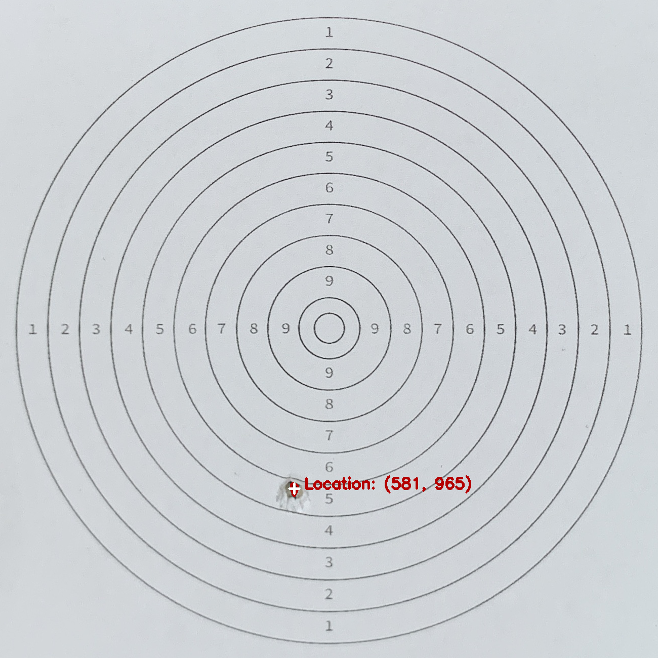 Shot Location
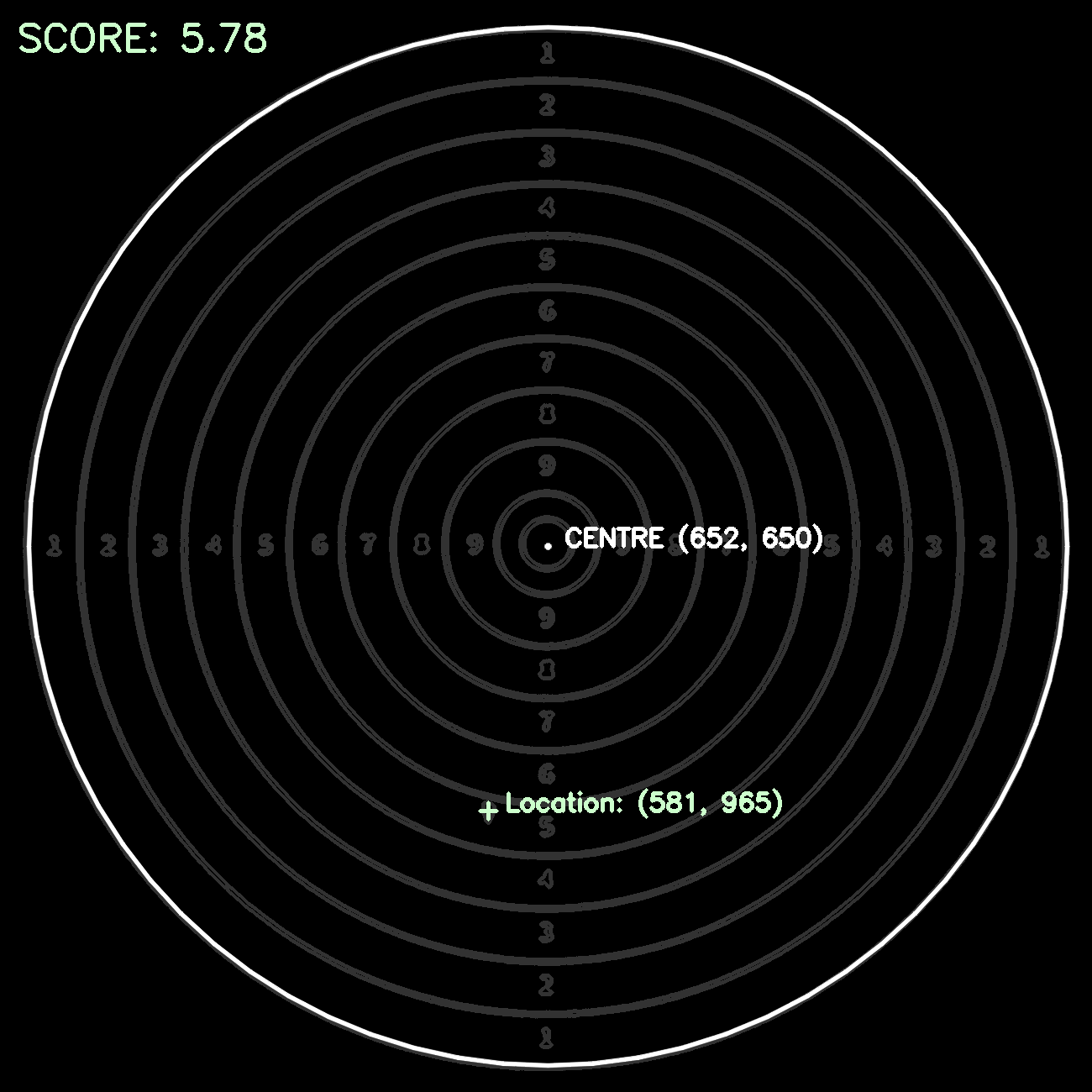
Based on the data extracted above:
- target centre location
- shot location
- distance between rings
A score can be calculated as follows: by dividing the euclidean distance between the shot location and target centre with the average distance between each ring, It should be noted that the maximum score per shot is 10.9 points, and the radius of the 10th and 9th rings are halved. Reference to ISSF - Olympic Games Championships
1
2
3
4
5
6
7
8
9
10
void ShootingScore::computeShootingScore()
{
    // compute shot distances
    shot_distance = cv::norm(target_centre - shot_location);

    double distance = total_radius / 10;
    double num_distances = (shot_distance / distance);

    score = 11 - num_distances;
}
This is the final result image that can be displayed to users.
 Result Drawn